Right down to the bones
More and more rebuilders are further refining production models. “Super enhancing” is what they call this process, in which many subtleties are refined. For a show truck, the redesigned driver’s cab is particularly important. But how do you get it? Frank Hadel shows how you can professionally disassemble a model without damaging it.
If you look back at models that are now much older, you will notice their simplicity. For the most part, a passenger car in the H0 scale consisted of the body, the windows, and a simple base plate. Combined with four identical wheels on two steel axles, the construction effort remained manageable. But those days are long gone. Nowadays, a model consists of many parts and even if – as is the case with Herpa models – no glue is used, it is often difficult to disassemble the model without causing any damage.
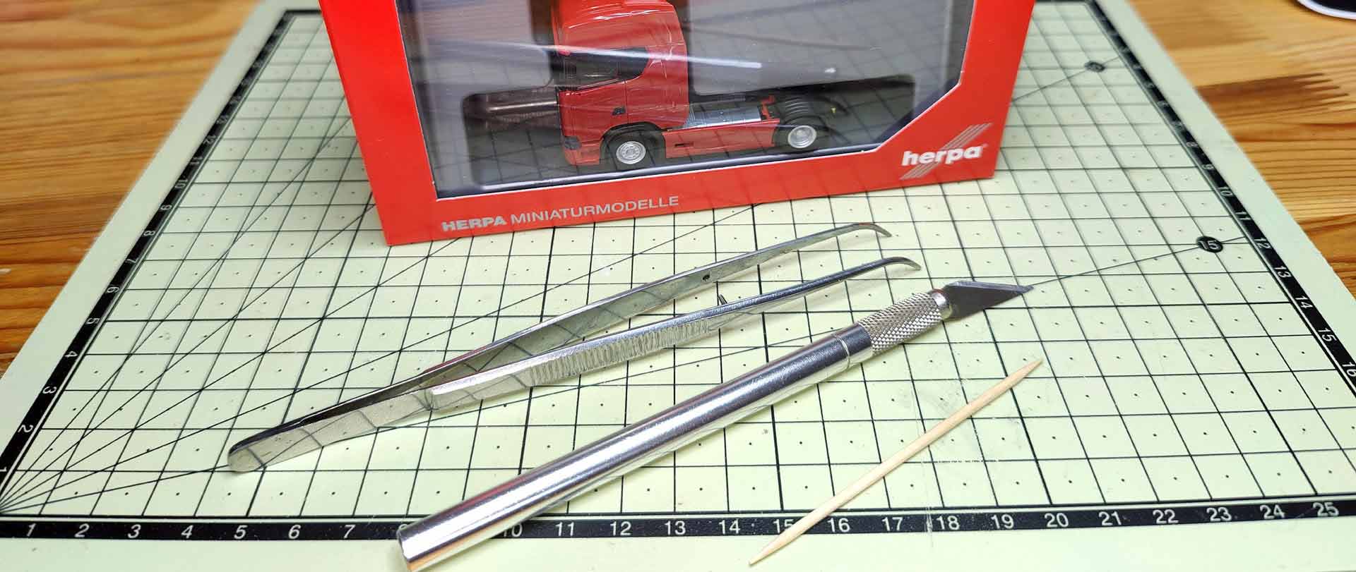
Often, there are only a few key parts that hold everything together. But which ones? What is important is to remain calm, be patient, and have a good feel down to the last component. If you proceed too briskly, the fine pins of individual parts will break or tear off and get stuck in the holes. What breaks off must be glued together later, and this does not improve the model. Fine tweezers, scalpels, and toothpicks have proven effective, thin paper towels used as a base avoid scratches. The car bodies from highly polished molds do not forgive rough handling.
The first steps
Text and Photos: Frank Hadel
Find key part
Often, there are only a few key parts that hold everything together. But which ones? What is important is to remain calm, be patient, and have a good feel down to the last component. If you proceed too briskly, the fine pins of individual parts will break or tear off and get stuck in the holes. What breaks off must be glued together later, and this does not improve the model. Fine tweezers, scalpels, and toothpicks have proven effective, thin paper towels used as a base avoid scratches.
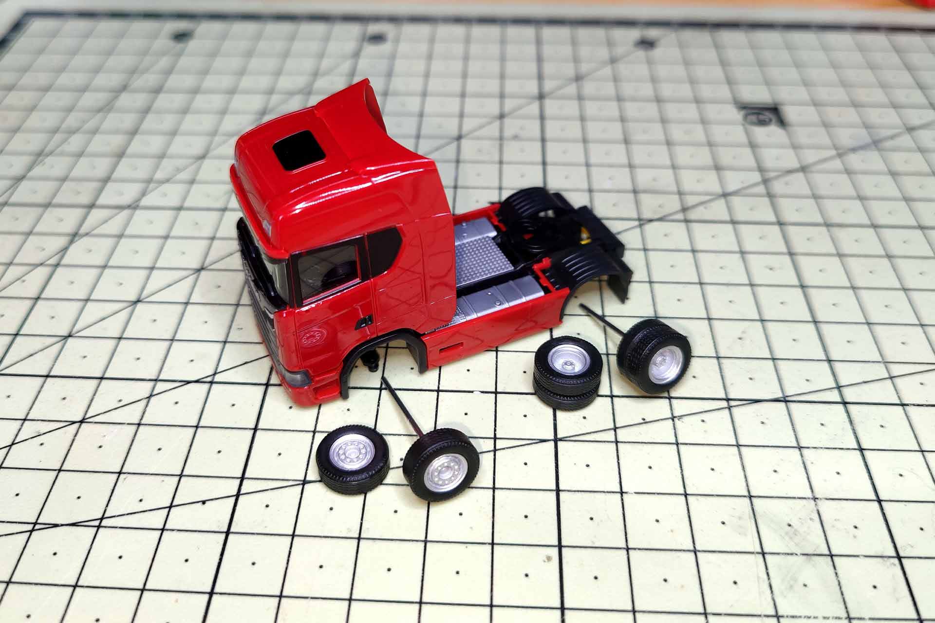
First, the rims are detached from the axles and pulled out of the chassis.
Over the sun visor to the goal


The two-part sun visor already becomes a challenge and has to be levered out from the bottom to the front. Next comes the radiator grille, probably the most complex unit of all models at the moment. Regardless of whether they are monochrome or multicolored, the grille bars and the ventilation grille are separate parts that have to be levered forward one after the other, sideways, with a scalpel. The grille features four pins to be disengaged step-by-step on both sides.
Four pegs hold the grille


Now, the rear element with the fine ventilation grilles is levered forward in the same way. It carries the upper part with the Scania emblem. The signet can, but does not have to, be separated.
The cab


Thus prepared, the main headlights including the inner part with the chrome headlight graphic are pulled off. This step allows access to the bumper via the pins (red dots). Two hints: inside the bumper sits another glass part for the small fog lights. During disassembly, the bumper is tilted slightly upwards to allow the access steps to bypass the inner part. Once all parts of the front are detached, the cabin can be lifted off. For further disassembly, reach with the scalpel behind the cab doors to the door openers. Slightly pressed inwards, the lower part with the wheel housings can be pulled out of the cabin. Without further anchors, the interior fittings and the windows follow.
The chassis
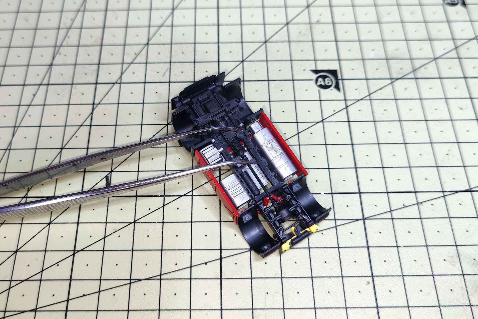
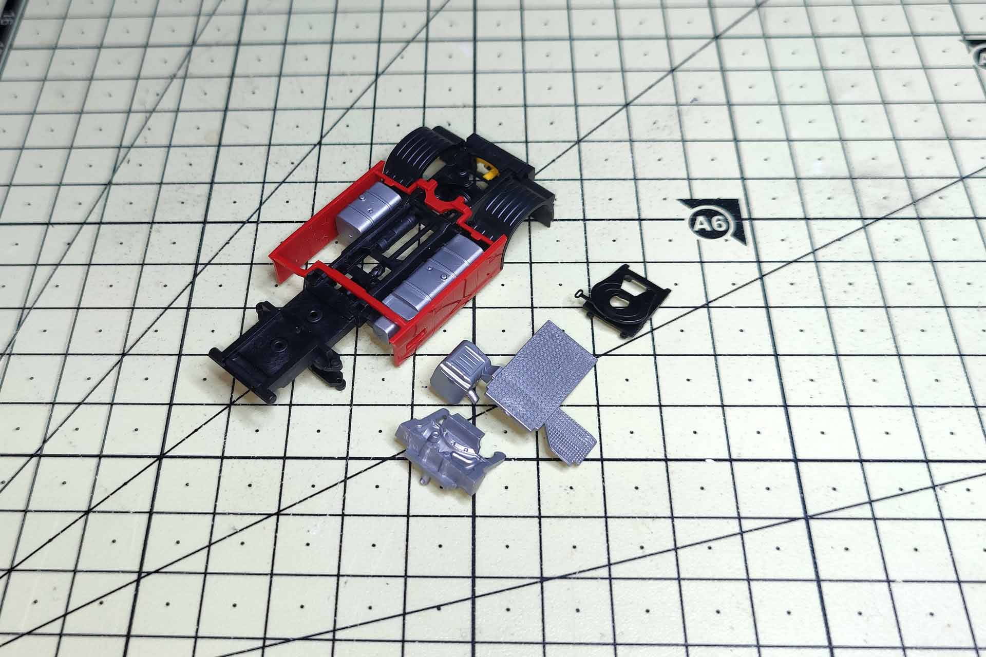
The indicated engine clings to the chassis from above and must be levered open carefully. These clamps are rigid and break easily. The walkway behind the cabin is detached from the bottom to the top without any problems. The fifth wheel plate is held in place by four clips, the front ones of which are pressed towards the rear under pressure. With the second clip, the plate pops off the chassis, releasing the side panel.
Final steps
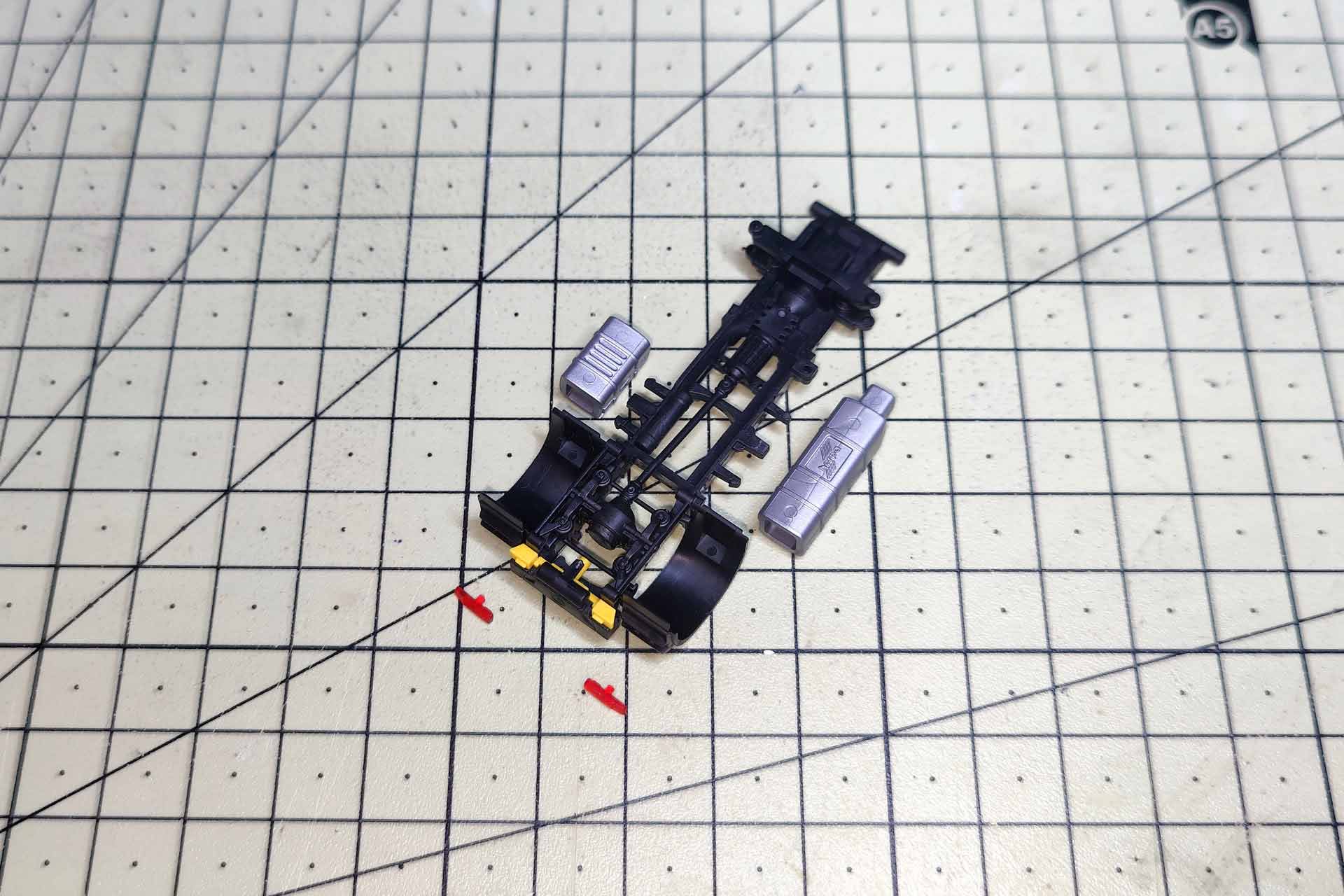
The taillights are quick to pull off, as are the side attachments. The holder for the yellow brake pads is attached. The brake pads can also be removed. In the area of the drive axle, the lower part of the two-part chassis has four clips, similar to the fifth wheel plate. They are carefully unhooked. Finally, the two parts are folded apart towards the front. In the engine area, the two parts are once again inserted into each other. Finally, the wheel housing is separated from the chassis at the pins in the air bellows with a scalpel.
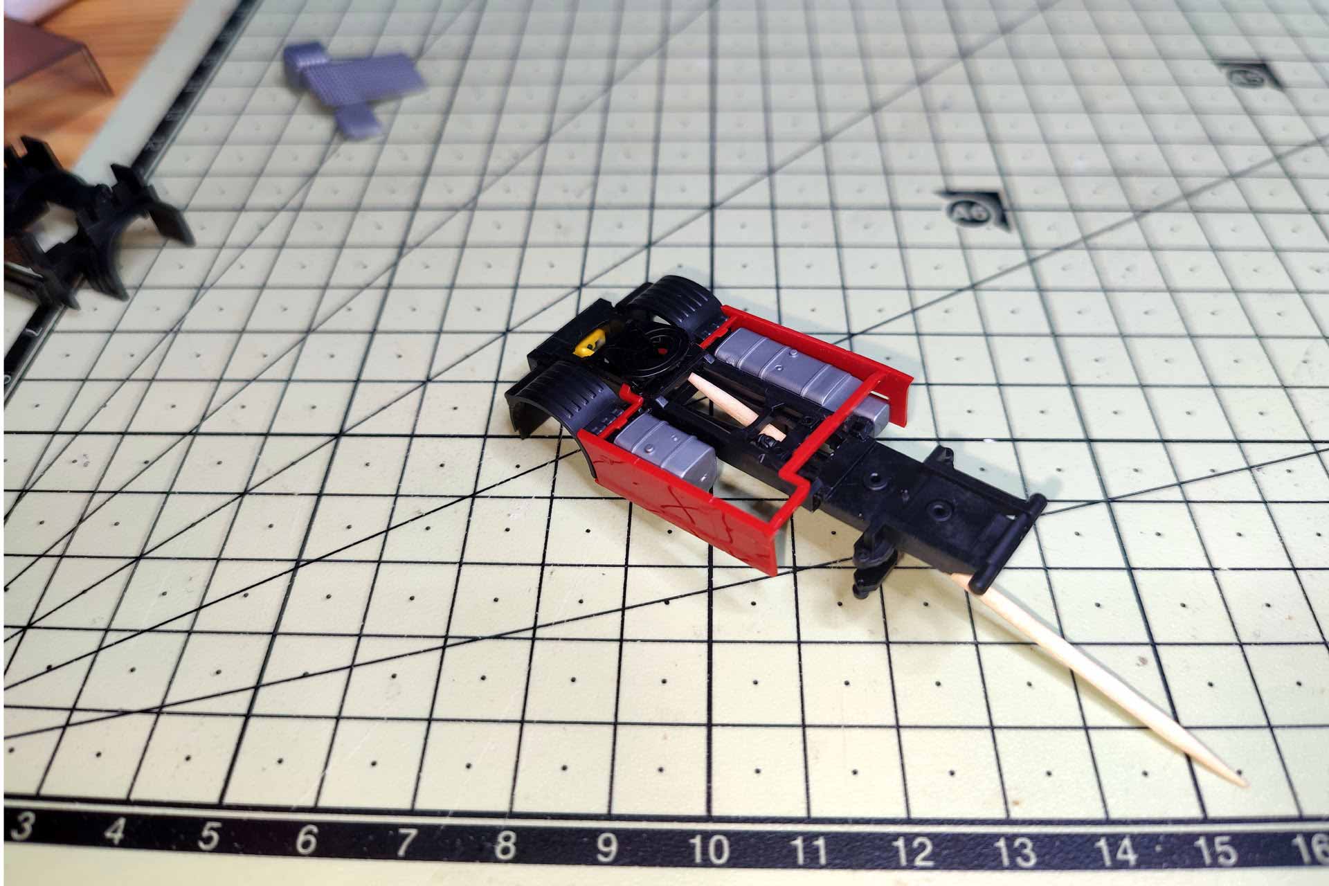
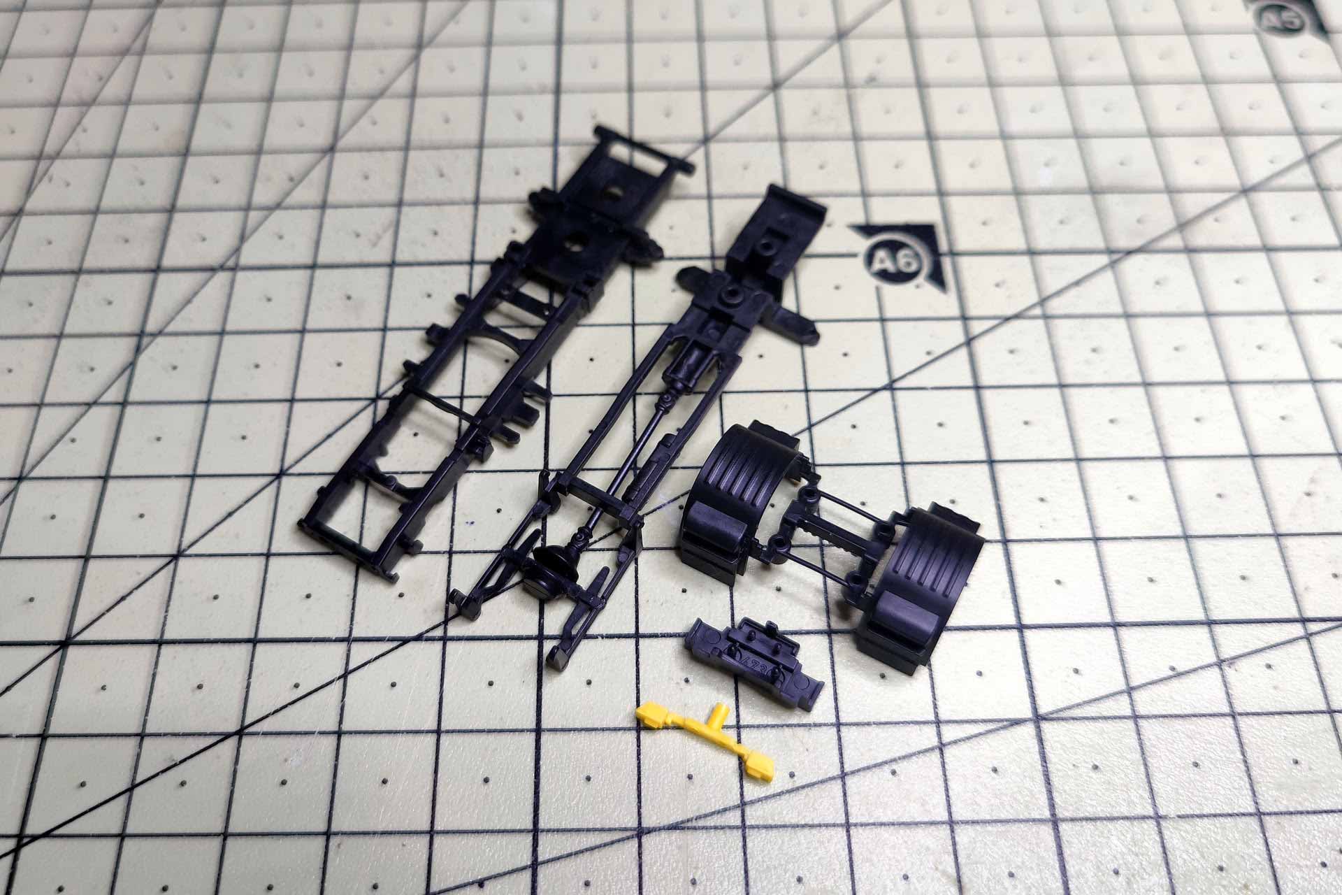
Basically always the same scheme
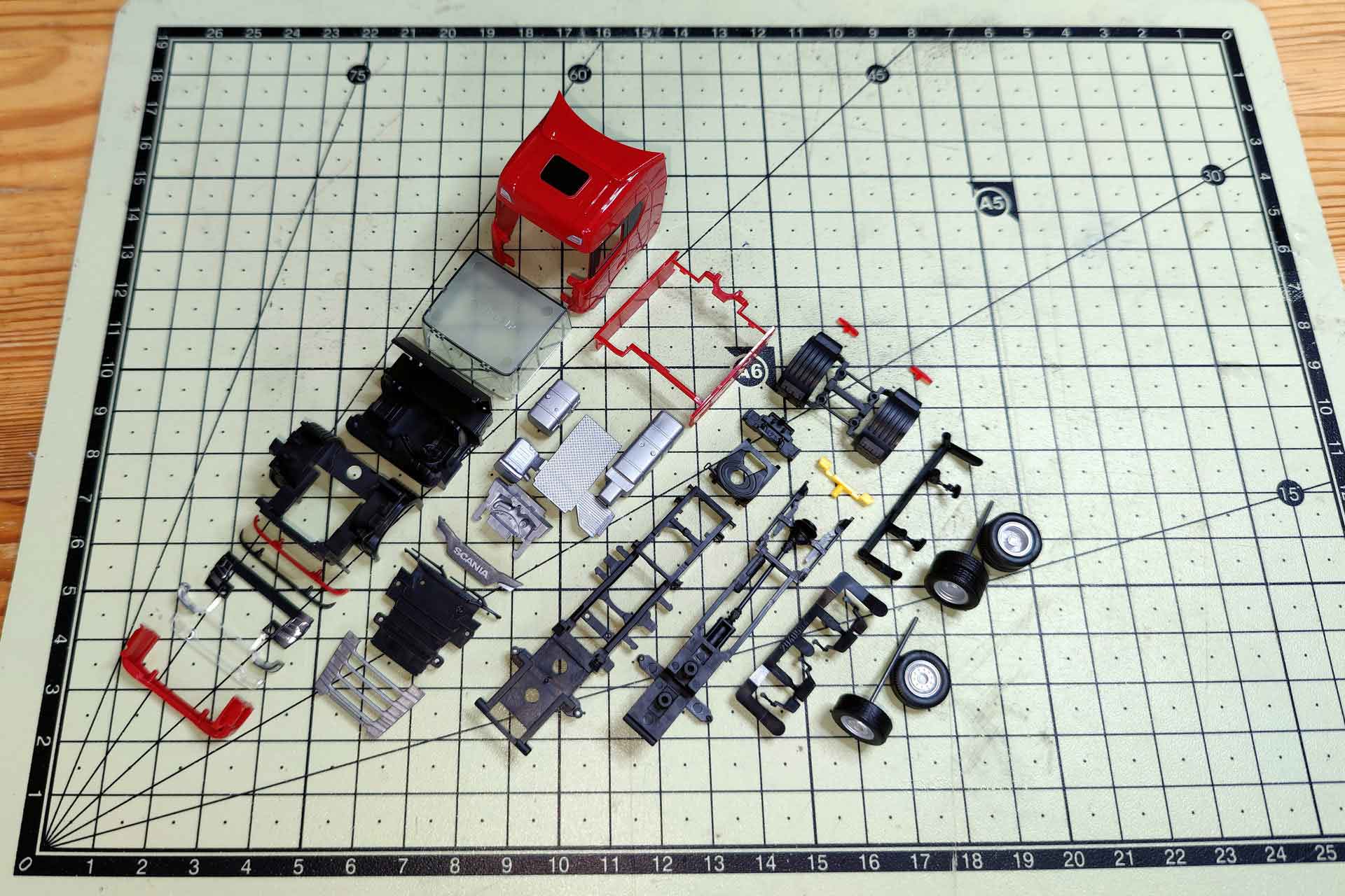
Now, the model, which has been disassembled into all its individual components, is available for designing your preferred model yourself. In general, it should be noted that other makes are also structured somewhat differently. However, the scheme with the mutually securing pins recurs. Models with tilting cabins are equipped with a replica of the complete engine. This drive unit is deeply inserted into the holes in the chassis with two longer pins (photo 12). In these constructions, the engine block also acts as a bridge to fix the wheel housings to the chassis. Good luck with the realization of your own dream models!